Step 2. I used some stiff plastic stock used for model train building found at hobby stores to create a mock-up of the adapter plate necessary. This is probably the most critical step of the whole process. Alignment of the caliper is absolutely critical to the performance of the final setup. I did not use any CAD or mechanical drawing is it was a matter of trial and error. Make a template test it out and make adjustments till I got it right. The adjustments made between templates vary by millimeters!!! A trick I used to improve the accuracy of the template was to drill the bolt holes slightly smaller then the mounting bolts. Since the template is plastic the bolt will easily thread itself through the plastic. Remember, 1-2mm is enough to screw they whole alignment up. Ideally you want the caliper to ride as close to the rotor's outer edge as humanly possible without physical contact, my goal was 2-3mm clearance.
Once you are satisfied with the template, transfer it to 1/4" thick stainless steel.
Step 3. Ideally you would then cut the material on a metal cutting band saw. But like most of you I do not own one and don't have the $$$ or space to get one. Here's the approach I took which only requires a hand held drill and rotary tool (aka Dremel).
My suggestion here is to punch mark the 4 mounting holes and drill them first. After drilling verify that they match the template 100%, if it's off don't waste your time cutting out the template and start a new one. Remember your working with ~1mm tolerances here.
Step 4. Hit it with a bench top grinder to clean up the edges. You might have to make some very small adjustments to the template as the plastic is more forgiving then the stainless. Have the caliper handy and test fit after each adjustment. Make small adjustments and test fit after EVERY adjustment.
What is critical to performance of the setup is the alignment of the 4 mounting holes. What is critical in the "looks" department is the profile/shape of the mounting adapter.
Step 5. Bling it. Using a palm sander sand it down with 120-grit automotive type sandpaper (don't use the stuff for wood). Stainless is crazy hard so plan on about 1-2 hours of 120-grit, then go to 220 for another hour, then 320/400 for another hour. Then hit it with a buffing wheel and buffing compound made for stainless. I used a high speed drill with a 4" sewn buffing wheel. After the compound, use I used a new 4" sewn buffing wheel with Mother's aluminum polish.
After sanding:
After buffing:
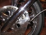
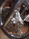
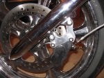
Step 6. Install the bracket on the forks, I used the factory bolts with nylon lock nuts. You then have to shim the caliper so that it's perfectly centered over the rotor. Harley rotors don't "float" like the stock caliper, they are fixed mounted and have pistons on both sides of the caliper whereas the stock only has pistons on one side of the caliper.
On my setup I ended up with 2.7mm worth of shims (thin washers) to center the caliper. Every caliper and every bike is going to be different. Shim adjustments are made down to the 0.1mm level.
Step 7. Since I'm going from a 2-piston caliper to a 6-piston caliper the stock master cylinder does not push enough brake fluid. The stock master cylinder worked but lever travel was way too much and the lever bottom out on the grip at full compression. Fix...Upgrade to a VTX-1800 master cylinder. The stock 1300 master has a 11mm piston bore and the 1800 master has a 14mm piston bore size. As a nice added bonus, the 1800 one I ordered came with a nice machined finish whereas my stock one was painted. The only downside is that now it doesn't match my clutch lever, though it's not that noticeable.
New master cylinder:
Step 8. Drink a beer.
Addendum to Step 6, once the caliper is shim'ed correctly you have to trim the caliper mounting bolts for rotor clearance. Remember that these bolts are grade-8 so just don't replace them with new ones unless the replacements are also grade-8.


") Need more custom one-off work on this forum!!!!
Need more custom one-off work on this forum!!!!